

How to install your FishLung System
Unlock the Full Potential of Your FishLung® Unit with Our Effortless Installation Process!
Experience peace of mind as you embark on an easy, secure, and seamless installation journey for your premium fish care solution. Our concise eight-step installation guide has been thoughtfully crafted to ensure your FishLung® unit is up and running in no time.
Get ready to revolutionize your fish care practices with ease.
Click here to download the Installation Guide PDF and discover the power of FishLung® or check out our step-by-step video guide below:

SYSTEM COMPONENTS AND TUBING DIAGRAM
A) FishLung® Control Box
B) Final Stage Filter
C) Unibody Assembly
D) Moisture Separator Filter
E) O2 Nano Bubble Diffuser
F) (5) Isolation Valves
G) Control Box Strap, Screw and Washer
H) Unibody Screws
I) Diffuser Mounting Post
J) Water-Proof Adhesive
K) 15' 1/4" Tubing
L) 10 Amp Fuse and Holder
M) Inline Check Valve
N) Line T
O) Regulator

STEP 1: Component Check
Unpack box and ensure you have all the essentials as noted on the System Components list on the following page. Familiarize yourself with the components and layout.
Note: Remove tape from bottom of filter cartridges before installing to allow air flow.
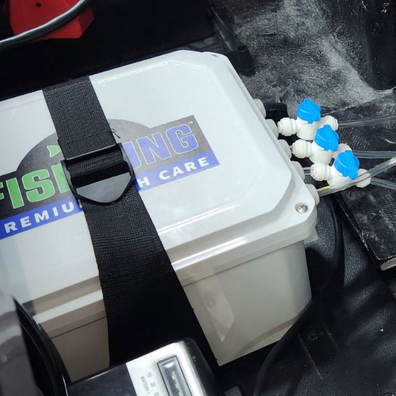
STEP 2: IDENTIFY LOCATION AND MOUNT CONTROL BOX
Identify a flat, secure surface for Control Box and mount using the provided strap system. Approximate dimensions: 13" (W) x 10" (H) x 7" (D). Leave room for hoses.
Note: Steps 2 and 3 can be swapped if needed. Every boat is different.

STEP 3: IDENTIFY LOCATION AND MOUNT UNIBODY ASSEMBLY
Identify a flat, secure surface for Unibody Assembly and mount using the provided screws and washers. Must be installed upright. Approx. dimensions: 11" (W) x 9.5" (H) x 6" (D).
Note: Allow space to be able to remove filter cartridges from unibody assembly..

STEP 4: INSTALL AND MOUNT O2 NANO BUBBLE DIFFUSER
Clean bottom of livewell. Attach Diffuser base to bottom of livewell with supplied water-proof adhesive. Allow 8-hours to cure. Once cured, attach stone and mounting post top using screw.
Note: Add small weight to base during curing period. Avoid power tools installing screw to avoid stripping.
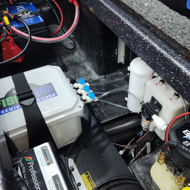
STEP 5: ARRANGE / INSTALL TUBING TO COMPONENTS
Follow the tubing diagram to connect tubing, line-T, regulator check valve (directional) and in-line valves. Position the shut-off valves for easy access.
Note: Drill ¼" hole above water line to install tubing to livewell. Seal hole with marine grade silicone. Tubing must be cut straight to avoid leakage. Regulator will be added to diffuser with higher flow to even the flow between both diffusers.
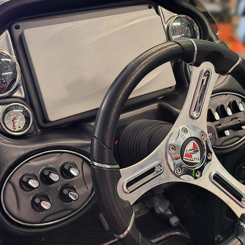
STEP 6: CONSOLE SWITCH CONNECTION
Locate an available fused switch on your boat's console for the FishLung unit. Add a switch if needed.

STEP 7: PROVIDE POWER TO FISHLUNG CONTROL BOX
Connect the Control Box power cord to the selected console switch, utilizing a 10 amp fuse and a reliable negative wire to the battery.

STEP 8: SYSTEM ACTIVATION AND TESTING
A. Open all five in-line valves.
B. Turn on FishLung® console switch.
C. Listen for 8-second cycle periods.
D. If water is in the livewell, observe the system running on/off in 4 min. cycles.
E. Close valves when finished using.